Planes in 3D space
A plane in 3D space can be thought of as a flat surface that stretches infinitely far, splitting space into two halves.
Loading 3D scene
Planes have loads of uses in applications that deal with 3D geometry. I’ve mostly been working with them in the context of an architectural modeler, where geometry is defined in terms of planes and their intersections.
Learning about planes felt abstract and non-intuitive to me. “Sure, that’s a plane equation, but what do I do with it? What does a plane look like?” It took some time for me to build an intuition for how to reason about and work with them.
In writing this, I want to provide you with an introduction that focuses on building a practical, intuitive understanding of planes. I hope to achieve this through the use of visual (and interactive!) explanations which will accompany us as we work through progressively more complex problems.
With that out of the way, let’s get to it!
Describing planes
There are many ways to describe planes, such as through
- a point in 3D space and a normal,
- three points in 3D space, forming a triangle, or
- a normal and a distance from an origin.
Throughout this post, the term normal will refer to a normalized direction vector (unit vector) whose magnitude (length) is equal to 1, typically denoted by
Starting with the point-and-normal case, here’s an example of a plane described by a point in 3D space
Loading 3D scene
The normal
We described this plane in terms of a single point
Loading 3D scene
If
This way of describing planes—in terms of a point and a normal—is the point-normal form of planes.
We can also describe a plane using three points in 3D space
Loading 3D scene
The triangle forms an implicit plane, but for us to be able to do anything useful with the plane we’ll need to calculate its normal
Loading 3D scene
As mentioned earlier, the normal
We can use
Loading 3D scene
By virtue of being parallel to the plane’s surface, the vectors
The cross product takes in two vectors
For example, given the vectors
Loading 3D scene
This explanation is simple on purpose. We’ll get into more detail about the cross product later on.
Because the edge vectors of the triangle,
Loading 3D scene
This gives us a normal
Loading 3D scene
Having found the triangle’s normal
Loading 3D scene
It doesn’t matter which of
Constant-normal form
There’s one more way to describe a plane that we’ll look at, which is through a normal
Loading 3D scene
This is the constant-normal form of planes. It makes lots of calculations using planes much simpler.
In the constant-normal form, the distance
This is a simplification. More formally, given a point
In getting a feel for the difference between the point-normal and constant-normal forms, take this example which describes the same plane in both forms:
Loading 3D scene
The green arrow represents
Translating from the point-normal to the constant-normal form is very easy: the distance
If you’re not familiar with the dot product, don’t worry. We’ll cover it later on.
The notation for
The normal
Distance from plane
Given an arbitrary point
Loading 3D scene
We can frame this differently if we construct a plane
Loading 3D scene
With two parallel planes, we can frame the problem as finding the distance between the two planes. This becomes trivial using their constant-normal form since it allows us to take the difference between their distance components
So let’s find
Loading 3D scene
With two distances
Loading 3D scene
So, to simplify, given a plane
The distance may be positive or negative depending on which side of the plane the point is on.
Projecting a point onto a plane
A case where calculating a point’s distance from a plane becomes useful is, for example, if you want to project a point onto a plane.
Given a point
Multiplying the plane’s normal
Loading 3D scene
The projection occurs along the plane’s normal, which is sometimes useful. However, it is much more useful to be able to project a point onto a plane along an arbitrary direction instead. Doing that boils down finding the point of intersection of a line and a plane.
Line-plane intersection
We can describe lines in 3D space using a point
Loading 3D scene
In this chapter, the line will be composed of the point
Loading 3D scene
Our goal will be to find a distance
We can figure out the distance
Let’s try projecting
We’ll visualize
Loading 3D scene
As
Here, the dot product comes in handy. For two vectors
where
Consider the dot product of
we can remove their magnitudes from the equation,
making the dot product of
For two vectors, the cosine of their angles approaches 1 as the vectors become increasingly parallel, and approaches 0 as they become perpendicular.
Since
With
Loading 3D scene
We can now get rid of
Putting this into code, we get:
Vector3 LinePlaneIntersection(Line line, Plane plane) {float denom = Vector3.Dot(line.normal, plane.normal);float dist = Vector3.Dot(plane.normal, line.point);float D = (plane.distance - dist) / denom;return line.point + line.normal * D;}
However, our code is not complete yet. In the case where the line is parallel to the plane’s surface, the line and plane do not intersect.
Loading 3D scene
That happens when
However, for many applications we’ll want to treat being almost parallel as actually being parallel. To do that, we can check whether the dot product is smaller than some very small number—customarily called epsilon
float denom = Vector3.Dot(line.normal, plane.normal);if (Mathf.Abs(denom) < EPSILON) {return null; // Line is parallel to plane's surface}
See if you can figure out why Mathf.Abs is used here. We’ll cover it later, so you’ll see if you’re right.
We’ll take a look at how to select the value of epsilon in a later chapter on two plane intersections.
With this, our line-plane intersection implementation becomes:
Vector3 LinePlaneIntersection(Line line, Plane plane) {float denom = Vector3.Dot(line.normal, plane.normal);if (Mathf.Abs(denom) < EPSILON) {return null; // Line is parallel to plane's surface}float dist = Vector3.Dot(plane.normal, line.point);float D = (plane.distance - dist) / denom;return line.point + line.normal * D;}
Rays and lines
We’ve been talking about line-plane intersections, but I’ve been lying a bit by visualizing ray-plane intersections instead for visual clarity.
Loading 3D scene
A ray and a line are very similar; they’re both represented through a normal
The difference is that a ray (colored red) extends in the direction of
Loading 3D scene
What this means for intersections is that a ray will not intersect planes when traveling backward along its normal:
Loading 3D scene
Our implementation for ray-plane intersections will differ from our existing line-plane intersection implementation only in that it should yield a result of “no intersection” when the ray’s normal
Since
if (D < 0) {return null;}
But then we’d have to calculate
If this feels non-obvious, it helps to remember that the dot product encodes the cosine of the angle between its two component vectors, which is why the dot product becomes negative for obtuse angles.
Knowing that, we can change our initial “parallel normals” test from this:
Vector3 LinePlaneIntersection(Line line, Plane plane) {float denom = Vector3.Dot(line.normal, plane.normal);if (Mathf.Abs(denom) < EPSILON) {return null; // Line is parallel to plane's surface}// ...}
To this:
Vector3 RayPlaneIntersection(Line line, Plane plane) {float denom = Vector3.Dot(line.normal, plane.normal);if (denom < EPSILON) {// Ray is parallel to plane's surface or pointing away from itreturn null;}// ...}
The
Note:
Plane-plane intersection
The intersection of two planes forms an infinite line.
Loading 3D scene
As a quick refresher: lines in 3D space are represented using a point
Loading 3D scene
Let’s take two planes
Finding the direction vector of
The magnitude of the cross product is equal to the area of the parallelogram formed by the two component vectors. This means that we can’t expect the cross product to be a unit vector, so we’ll normalize
This gives us the intersection’s normal
Loading 3D scene
But this is only half of the puzzle! We’ll also need to find a point in space to represent the line of intersection (i.e. a point which the line passes through). We’ll take a look at how to do just that, right after we discuss the no-intersection case.
Handling parallel planes
Two planes whose normals are parallel will never intersect, which is a case that we’ll have to handle.
Loading 3D scene
The cross product of two parallel normals is
As previously mentioned, for many applications we’ll want to treat planes that are almost parallel as being parallel. This means that our plane-plane intersection procedure should yield a result of “no intersection” when the magnitude of
Line PlanePlaneIntersection(Plane P1, Plane P2) {Vector3 direction = Vector3.cross(P1.normal, P2.normal);if (direction.magnitude < EPSILON) {return null; // Roughly parallel planes}// ...}
But what should the value of epsilon be?
Given two normals
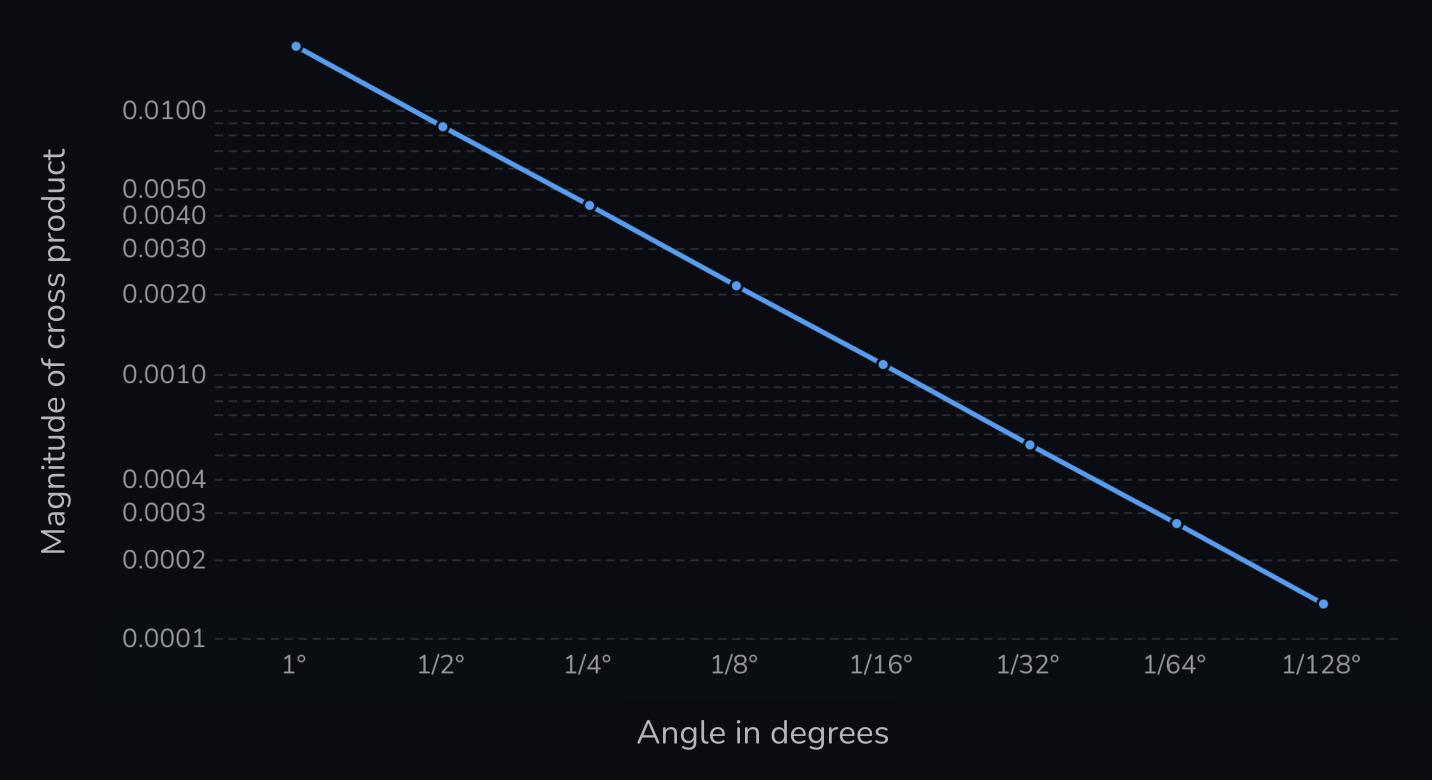
Both of the axes are logarithmic.
The relationship is linear: as the angle between the planes halves, so does the magnitude of the cross product of their normals.
So to determine the epsilon, we can ask: how low does the angle in degrees need to become for us to consider two planes parallel? Given an angle
If that angle is 1/256°, then we get:
With this you can determine the appropriate epsilon based on how small the angle between the planes needs to be for you to consider them parallel. That will depend on your use case.
Finding a point of intersection
Having computed the normal and handled parallel planes, we can move on to finding a point
Since the line describing a plane-plane intersection is infinite, there are infinitely many points we could choose as
Loading 3D scene
We can narrow the problem down by taking the plane parallel to the two plane normals
Loading 3D scene
Since the point lies on the plane parallel to the two plane normals, we can find it by exclusively traveling along those normals.
The simplest case is the one where
Loading 3D scene
When dragging the slider, notice how the tip of the parallelogram gets further away from the point of intersection as the planes become more parallel.
We can also observe that as we get further away from the point of intersection, the longer of the two vectors (colored red) pushes us further away from the point of intersection than the shorter (blue) vector does. This is easier to observe if we draw a line from the origin to the point of intersection:
Loading 3D scene
Let’s define
To solve this asymmetric pushing effect, we need to travel less in the direction of the longer vector as the planes become more parallel. We need some sort of “pulling factor” that adjusts the vectors such that their tip stays on the line as the planes become parallel.
Here our friend the dot product comes in handy yet again. When the planes are perpendicular the dot product of
Let’s give the dot product
The perfect pulling factors happen to be the distance components
Consider why this might be. When
which we know yields the correct solution.
In the case where
Because the absolute values of
This means that the magnitude of our vectors will become more equal as the planes become parallel, which is what we want!
Let’s see this in action:
Loading 3D scene
The vectors stay on the line, but they become increasingly too short as
Yet again, we can use the dot product. Since we want the length of the vectors to increase as the planes become parallel, we can divide our scalars
The result of this looks like so:
Loading 3D scene
Using
However, notice what happens when we visualize the quadrants of the parallelogram:
Loading 3D scene
As the planes become more parallel, the point of intersection approaches the center of the parallelogram.
In understanding why that is, consider the effect that our denominator

This means that when we scale the component vectors of the parallelogram by
it has the effect of scaling the area of the parallelogram by:
To instead scale the area of the parallelogram by
Squaring allows us to remove
With this, our scalars
which scales the parallelogram such that its tip lies at the point of intersection:
Loading 3D scene
Putting all of this into code, we get:
float dot = Vector3.Dot(P1.normal, P2.normal);float denom = 1 - dot * dot;float k1 = (P1.distance - P2.distance * dot) / denom;float k2 = (P2.distance - P1.distance * dot) / denom;Vector3 point = P1.normal * k1 + P2.normal * k2;
Based on code from Real-Time Collision Detection by Christer Ericson
Which through some mathematical magic can be optimized down to:
Vector3 direction = Vector3.cross(P1.normal, P2.normal);float denom = Vector3.Dot(direction, direction);Vector3 a = P1.distance * P2.normal;Vector3 b = P2.distance * P1.normal;Vector3 point = Vector3.Cross(a - b, direction) / denom;
How this optimization works can be found in chapter 5.4.4 of Real-Time Collision Detection by Christer Ericson.
This completes our plane-plane intersection implementation:
Line PlanePlaneIntersection(Plane P1, Plane P2) {Vector3 direction = Vector3.cross(P1.normal, P2.normal);if (direction.magnitude < EPSILON) {return null; // Roughly parallel planes}float denom = Vector3.Dot(direction, direction);Vector3 a = P1.distance * P2.normal;Vector3 b = P2.distance * P1.normal;Vector3 point = Vector3.Cross(a - b, direction) / denom;Vector3 normal = direction.normalized;return new Line(point, normal);}
By the way, an interesting property of only traveling along the plane normals is that it yields the point on the line of intersection that is closest to the origin. Cool stuff!
Three plane intersection
Given three planes
- All three planes are parallel, with none of them intersecting each other.
- Two of the planes are parallel, and the third plane intersects the other two.
- All three planes intersect along a single line.
- The three planes intersect each other in pairs, forming three parallel lines of intersection.
- All three planes intersect each other at a single point.
Loading 3D scene
When finding the point of intersection, we’ll first need to determine whether all three planes intersect at a single point—which for configurations 1 through 4, they don’t.
Given
When I first saw this, I found it hard to believe this would work for all cases. Still, it does! Let’s take a deep dive to better understand what’s happening.
Two or more planes are parallel
We’ll start with the configurations where two or more planes are parallel:
Loading 3D scene
If
And since the dot product is a multiple of the magnitudes of its component vectors:
the final result is zero whenever
This takes care of the “all-planes-parallel” configuration, and the configuration where
Loading 3D scene
With that, let’s consider the case where
Let’s take the specific case where
Loading 3D scene
Here the cross product
Loading 3D scene
Since
This also holds in the case where
Parallel lines of intersection
We’ve demonstrated that two of the three normals being parallel results in
Loading 3D scene
As we learned when looking at plane-plane intersections, the cross product of two plane normals gives us the direction vector of the planes’ line of intersection.
Loading 3D scene
When all of the lines of intersection are parallel, all of the plane normals defining those lines are perpendicular to them.
Yet again, because the dot product of perpendicular vectors is 0 we can conclude that
We can now begin our implementation. As usual, we’ll use an epsilon to handle the “roughly parallel” case:
Vector3 ThreePlaneIntersection(Plane P1, Plane P2, Plane P3) {Vector3 cross = Vector3.Cross(P2.normal, P3.normal);float dot = Vector3.Dot(P1.normal, cross);if (Mathf.Abs(dot) < EPSILON) {return null; // Planes do not intersect at a single point}// ...}
Computing the point intersection
We want to find the point at which our three planes
Loading 3D scene
Some of what we learned about two-plane intersections will come into play here. Let’s start by taking the line of intersection for
Loading 3D scene
When
Loading 3D scene
This vector—let’s call it
We can find
The latter vector can be found via the equation
where
With
Let’s see what it looks like:
Loading 3D scene
Hmm, not quite long enough.
As it turns out, we’ve already computed this scaling factor:
The product of
We want the
Loading 3D scene
Fully expanded, the equation for
Bam! The problem is now reduced to traveling along the direction of the line intersection until we intersect with
Loading 3D scene
We could use our knowledge of line-plane intersections to solve this, but there is a more efficient approach I want to demonstrate.
It involves finding a scaling factor for the direction vector
There’s one observation we can make that simplifies that. Since
Loading 3D scene
With that, consider the vector
Loading 3D scene
If
Loading 3D scene
As
One thing to note as well is that even when
Loading 3D scene
But we’re getting ahead of ourselves—we won’t need to normalize
Having defined
Earlier I mentioned that we could think of
Since the dot product is a multiple of the magnitudes of its component vectors,
- it normalizes
, and - it increases the length of
as it becomes less parallel with .
So
Loading 3D scene
We’ve got our solution! Let’s do a quick overview.
We define
We’ll redefine
Our denominator,
With this, we find our point of intersection
Which fully expanded becomes:
Putting this into code, we get:
Vector3 ThreePlaneIntersection(Plane P1, Plane P2, Plane P3) {Vector3 dir = Vector3.Cross(P2.normal, P3.normal);float denom = Vector3.Dot(u);if (Mathf.Abs(denom) < EPSILON) {return null; // Planes do not intersect at a single point}Vector3 a = P2.normal * P3.distance;Vector3 b = P3.normal * P2.distance;Vector3 V = Vector3.Cross(P1.normal, a - b);Vector3 U = dir * P1.distance;return (V + U) / denom;}
Parting words
Thanks for reading!
A whole lot of hours went into writing and building the visualizations for this post, so I hope it achieved its goal of helping you build an intuitive mental model of planes.
Massive thanks goes to Gunnlaugur Þór Briem and Eiríkur Fannar Torfason for providing invaluable feedback on this post. I worked with them at GRID; they’re fantastic people to work with and be around.
— Alex Harri
PS: If you’re interested in taking a look at how the visualizations in this post were built, this website is open source on GitHub.
Further reading
I highly recommend checking out Real-Time Collision Detection by Christer Ericson. If you’re building applications using 3D geometry, it will prove to be an incredibly useful resource. This post would not exist were it not for this book—especially the two chapters on the intersections of planes.
I recently analyzed the edit performance in Arkio and noticed that a method for solving three-plane intersections took around half of the total compute time when recalculating geometry. By implementing the more efficient method for three-plane intersections described in the book, we made the method ~500% faster, increasing Arkio’s edit performance by over 1.6x. Crazy stuff!
I started writing this post to understand how the three-plane intersection method worked. However, I felt that readers would need a better foundation and understanding of planes for this post to be of any value. In building that foundation, this post ended up quite a bit longer than I intended.
Anyway, it’s a great book. Check it out!
To be notified of new posts, subscribe to my mailing list.